The plastic injection molding process relies on good tooling design, construction, tuning and validation.
W&S has tool making capabilities on both our Sydney and Johor plants. Where necessary, we also draw from our list of carefully selected contract tool rooms.
The Tool Making Process

Before beginning the tool making process we carefully examine the component design.
Our project team review,
- Draft angles to ensure that the component will release from the tool
- Thickness analysis to look for changes in thickness that might cause voids, sinks, flow lines, weld lines, streaks etc.
- Rib versus wall thickness analysis to predict sinks and warpage
- Features of the component that cause complexity in the tooling such as internal threads which will require a mechanical unscrewing device and severe undercuts that will require side cores.
After agreeing upon any recommended changes with our customer we can commence the design of the tool.
Manufacture of the tool
Following a check of the tool design and, if required, sign off by the customer, the manufacture of the tool begins.
During the tool design process, the steel blocks and purchased components of the tool have been ordered and and these arrive as required by the project plan.
With final approval of the design of the tool, machining (shaping) of the metal blocks begins.
The majority of machining of the steel is done using a computer numerical controlled (CNC) milling machine or machining center.
Tool Design Process
When starting with a white screen on the CAD software, the designer first considers the best orientation of the component in the tool. If the tool is not oriented correctly it can result in unsightly marks such as gates and ejector pin witness lines on seen faces of the component that are aesthetically important.
Parting lines, gate and ejector pin locations are determined, often in consultation with the customer.
If necessary a mold flow analysis can be performed to predict cavity fill time, cooling time, warpage, weld lines, sinks, hot spots on the tool. Experiments can be conducted during this process (before metal is cut) to optimize component and tool design.


Tool Glossary
Gate
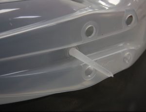
The gate is the point of entry of the plastic into the component.
There are many different types of gate available for our tool designers to chose from including:-
Tab Gate
Ring Gate
Pin Gate
Tunnel Gate (sub gate)
Horn Gate
Hot tip
Valve Gate
The correct gate for your application will depend on multiple factors such as cost, aesthetic requirements, mechanical requirements, material requirements and others.
Our engineers will work with you to determine the most appropriate gate.
Sprue
This is a tapered cylinder that is molded onto the cold runner or directly onto the component and later removed and scrapped or recycled.
Its purpose is to provide a path from the nozzle of the injection molding machine to the component.
The removal of the sprue from the component can leave an unattractive raised mark which can be improved by machining processes such as spot facing.
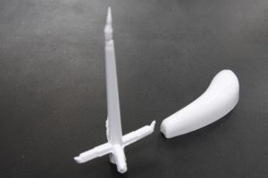
Cold Runner
This is a piece of plastic that is required to deliver the plastic from the barrel of the molding machine to the component cavity within the mold. It is ejected from the mold with the component and is either recycled or scrapped.

Hot Runner
A manifold system that keeps the plastic molten at closely controlled temperatures between the injection molding machine’s nozzle and the component gate.
This system is usually used in high volume components where scrap would be significant contributor to cost.
Hot runners typically have a neater gate vestige particularly when valve gates are used.

Water circuits
The plastic molding process involves injecting liquid plastic which may be as hot as 350°C into a metal tool (mold). If the tool is not cooled in some manner, its temperature will rise gradually until it can no longer cool the components adequately.
The tool must have a system of channels or drilled holes interconnected throughout to carry water or oil for the purpose of maintaining constant temperature of the tool during the process.
Some plastics require a very cold tool to solidify the molten plastic as rapidly as possible whereas other plastics require that they be controlled at a much higher temperature to ensure that the plastic solidifies and cools slowly allowing them to enter the solid state with the correct crystalline structure.
In some instances, heater cartridges are installed in the tool to raise the temperature of the metal above what is possible with pressurized water or oil.