We recently completed another major automation project and want to share our story.
A value analysis and value engineering project (VA VE) run cooperatively with a customer resulted in several identical two cavity molds being replaced with a four cavity mold. The success of this project inspired us to seek other ways of reducing the cost of manufacture of this injection moulded and pad printed component.
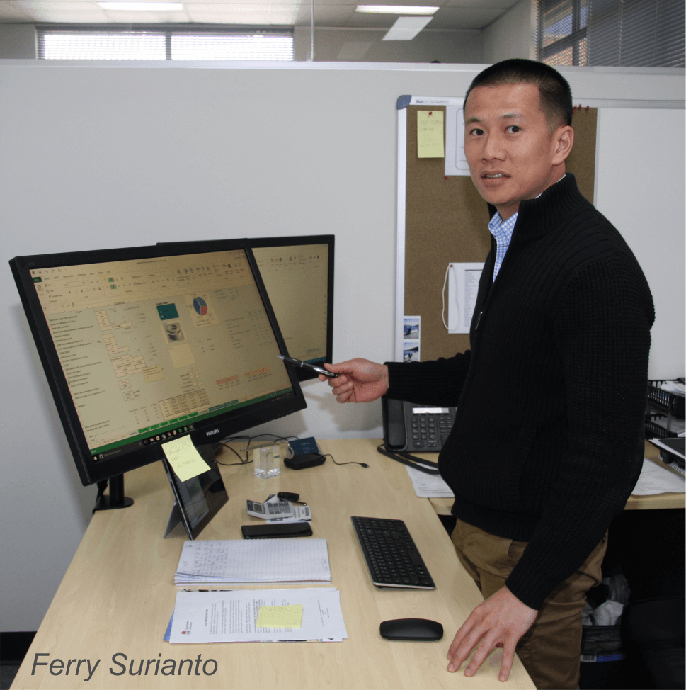
Our Operations Manager, Dale Berthon-Jones worked closely with Continuous Improvement Manager, Ferry Surianto to analyse the entire process flow and analyse where there was potential for savings.
The video below shows the final cell in operation and the images and text further below tell the complete story.
The result was a bold plan to create a fully automated cell to mold the components, print them, perform quality control checks and bag components by cavity, all with no direct human involvement.
An automation team was created and tasked with the project.
It was determined at the outset that the project would be best managed in stages beginning with the printing process.
Stage 1 required several pieces of equipment including a four station pad printer, an ABB 6 axis robot and two roller conveyors.
The team agreed that the moulding and printing processes should be linked rather than integrated so that if the printing process is interrupted it does not interrupt the moulding process. Moulding can continue uninterrupted while the printing process is cleaned or tuned.
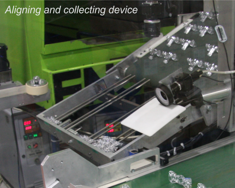
An aligning and collecting stage was designed and fabricated in house and attached to the output end of an integrated belt conveyor.
This collector allows enough parts to be stored to provide time for an operator or technician to service the printing machine when required.
To ensure that we have complete flexibility in programming the complex ABB robot Ferry spent several days training at ABB Sydney learning how to program and operate the robot. On his return, he shared his knowledge with Dale and others in the team to maximise our overall capabilities.
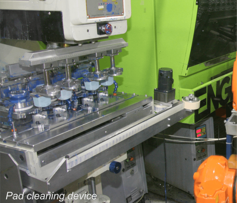
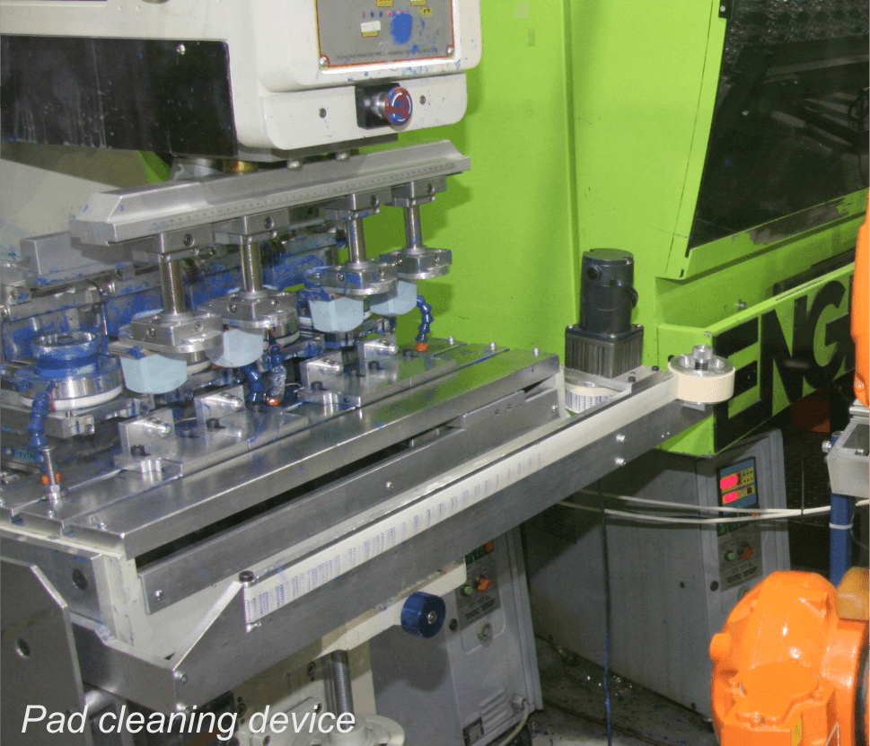
The team elected to design and build their own automated cleaning device for the silicon pads used to apply the printed images to the parts. It required pneumatic and electrical integration to the printer and the robot. Once again everything was designed and built in house.
With stage one equipment prepared and installed, we built up stock of production components and took the moulding machine out of the production schedule to perform testing.
As expected, some design changes and tuning were required and these were quickly executed. The result was an outstanding success, so much so, that after careful validation and with 100% operator monitoring it was brought into production and stage 2 was started.
Stage 2 involved the implementation of a vision quality checking system and the manufacture of a device to utilise the outputs of the system to direct accepted and failed components appropriately.
Because this was a new process to us Ferry was once again dispatched to become an expert.
This stage two process intercepts the components during the unloading from the printer and uses images captured by a high speed, high definition camera system to analyse them against a reference image.
The first camera captures an image of the print and from this, measures its position, counts the pixels in the printed image and references these to presets in the program. It then provides an output to accept or reject each of four printed components individually.
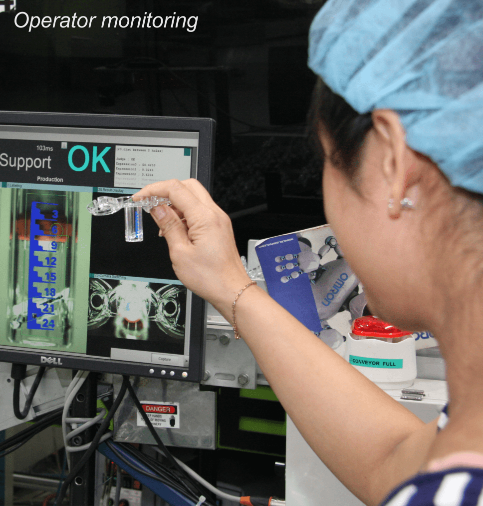
The second camera measures the distance between two holes molded into the component to determine if there has been any drift in process.
During this stage if any part is rejected, the robot was programmed to place all four components ‘off line’ on the output conveyor. The operator could easily identify which components the system had rejected and remove and inspect them.
At the completion of the successfully validated Stage 2, we still had the need for 100% of an operator in the process. Ferry was under pressure to move into stage three which would integrate a gate system at the point of removing the components from the robot end of arm.
This system allows accepted components to load onto the belt conveyor while rejected components are redirected to another channel for inspection by an operator at a later time.
Stage three also integrated a purchased carrousel device to allow bagging of each component by cavity with the automatic indexing of the bags when full. With this, the system was complete. With human involvement only required for about 6 minutes per hour the results met the original goals of the team.
Watch the video below to see the result of this outstanding work.
