A recent project involved the assembly of molded components with a specification for fitment that was difficult, if not impossible, to measure.
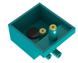 The specification referred to the fit of the two yellow components within the tubes as follows:-
“PULL-OUT” FORCE OF PLUG IN BODY MUST BE >6.6N”
This provided us with a challenge.
How do we measure the pull out force accurately?
Consider:-
- The hole in the center of the plug component is less than 1 mm and there is no access from behind, so it is difficult to use for any non-destructive testing.
- If we screw anything into the center hole of the plug component, the compression of the screw will increase the interference compression of the two components possibly giving a false pass.
- If we grip the plug component on the top flange, it will alter the interference compression of the two components and may elongate the part when a tensile (pulling) force is applied, once again giving a false reading.
- All of the above tests are destructive and the assembly specification calls for regular testing which would result in significant waste of assemblies which cannot be recycled.
Solution
 Our team came up with an innovative solution whereby we correlate the force required to insert the component with the force required to remove it.
We determined that if a minimum force of 45N is achieved during the insertion of the component, it would achieve much greater than the “PULL-OUT” force of 6.6N.
Because the components must be assembled using a mechanical press we determined that we could build a press with the following characteristics:-
- It could measure the maximum force achieved during the insertion of the plug
- It could measure every assembled component (as opposed to quality checks done to typical AQL requirements)
- It could provide an alarm if the specified force is not achieved.
The team decided to use a servo driven cylinder and utilise the feedback provided by it to calculate the force needed to move to a set position.
The cylinder moves to a fixed position at least 0.1mm before full insertion. The reported force to move to this position must be more than the set minimum (45N) or the machine will stop and report “LOOSE” and less than a set maximum (200N) or the machine will stop and report “TIGHT”.
Once it has a good reading the servo-cylinder moves to a final position (what we call overdrive) with full force to ensure the part is fully home.
The team found that the data from the servo cylinder was not as accurate or reliable as the supplier had promised so they added a load cell to the system to improve it.
The minimum required force is established experimentally by inserting at known force without overdrive and determining the resulting pull out force (destructively) which required the design of a special tool for pulling the part out.
Once the machine alarms, it stops with the press down and requires a reset button to restart the process so that the operator is less likely to accidentally place a failed component with those that have passed.

Later it was discovered that a 4th component that had been inserted by hand had a tendency to spring back out unless very firmly pushed home and might be missed out altogether. We were able to utilise the machine to test if this component was present and to use the same force as was used to insert the plugs to push the other component home. If this part is absent the machine will stop with an alarm.


We currently have three of these machines in full time production, two operate 24 x 6.
We have had no reports of components loose, falling out or missing.
This was a successful solution to an interesting challenge.